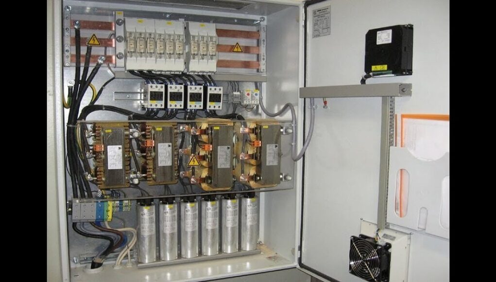
Is it possible to add a power factor correction capacitors to worsen the Power Factor? It sure is, and the starting point for understanding this puzzle is the difference between Displacement Power Factor (DPF) and Total Power Factor (PF). Also, you may ruin your capacitors or waste your investment if you don’t understand the difference.
In one fundamental sense, the Total Power Factor and Displacement Power Factor are the same. It is the ratio of real power to apparent power or the percentage of watts to VA. The classic concept of Displacement Power Factor is known as Power Factor. You can also call it the power factor at the fundamental frequency. The total power factor, abbreviated as power factor (PF), now includes the effects of primary and harmonic currents (also known as true PF or distortion PF).
Therefore, in the presence of harmonics, the PF is always less than the Displacement Power Factor and can represent the overall system efficiency more accurately than the Displacement Power Factor alone. Strictly speaking, the term “power factor” refers to total PF, but in practice, you can also use it to refer to DPF. This introduces some confusion in the energy factor discussion. Clear what you are talking about first.
Table of Contents
Displacement Power Factor
The drop in DPF is caused by the reactive power (voltage amplifier reactive power or VAR) required by the motor load. The system requires power, measured in volts amperes (VA), to supply VARs and watts. The higher the need for VAR technology, the higher the VA requirement and the smaller the DPF. The cost of VAR is included in the power factor penalty fee. Utilities often charge extra for a Displacement Power Factor below a certain level. Actual numbers vary widely, but typical numbers range from 0.90 to 0.95. The power factor correction capacitors are installed to reduce VAR due to motor load. At the plant and utility level, they release upstream system capacity for other uses. That was the crux of the PF story. It’s a relatively well-known issue with a reasonably simple solution.
Harmonics and Power Factor Correction Capacitors
The harmonics had a significant impact on the power factor correction capacitors. The motor and capacitor loads above are linear and do not generate harmonics. On the other hand, non-linear loads such as ASDS generate symmetric currents. Let’s take a step-by-step look at a manufacturer that puts a variable speed drive in a drive load. ASD produces large harmonic currents (V and VII in a 6-pulse transformer motor).
Suddenly the fuse in the current PF compensation cap started to blow. Since these are three-phase caps, they can blow only 1 of the three fuses. Now you have an unbalanced current and possibly an unbalanced voltage. The electrician replaces the fuse. They blow again. It puts on a larger fuse. Now the fuse has survived, but the capacitor has blown. Also, replace the capacitor. The same thing happens. What happened? Harmonics are high-frequency currents—the higher the frequency, the lower the cap resistance. The cover acts as a sink for the symmetrical currents.
Resonance Energy System
In the worst-case scenario, the inductive reactance of the transformer and the capacitive reactance of the PF compensation cap form a parallel resonant circuit with a resonant frequency at or near the harmonic frequency. The harmonic currents generated by the load excite the circuit in oscillation. Also, the current flowing in this circuit is several times the excitation current. The so-called “tank circuit” can seriously damage equipment and cause a low power factor. Conversely, this resonance condition often appears only when the system has light load, as they remove the damping effect of the resistive loads. In other words, we have what audiophiles call “high Q” circuits.
Imagine you come to work on Monday and find that the cable insulation has melted. How can this happen on weekends when the system is barely under load? Ohm’s Law is canceled? Your energy system ran out of harmonics all weekend. It’s been a quiet party, but the next step is to clean up.
Begin with harmonic relaxation
The path to a correct solution begins with the measurement and attenuation of the harmonics generated by the drive. (One helpful tool for measuring harmonics and capacitance is the Fluke 43B Power Quality Analyzer.) Usually you require a harmonic trap filter. Trap filters are installed locally on the drive line side. Its effect is very similar to traditional PF compensation caps in two ways. Reduce DPF and PF to localize the circulation of formed harmonics (usually v). Also, you should treat harmonic dilution and conventional DPF correction as a single-system problem. In other words, it manages the DPF and the total PF.


